
Quick start — first boot
Last updated 2026-05-09 · tested on hardware rev C, firmware 5.3.x
Everything from an unopened box to a working LTE uplink. Should take about fifteen minutes if you already have an activated SIM and the right APN.
In the box
- rCell 100 unit (DIN-rail clip already fitted on mine)
- 2 × LTE paddle antennas (SMA)
- 2-pin / 3-pin power terminal plug (screw type)
- Quick-start card (the paper one — this page is my expanded version)
You supply: an activated SIM (2FF / standard size), a 9–32 V DC supply, and an Ethernet cable to your laptop.
1. Insert the SIM
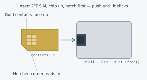
Power off before touching the SIM. The SIM 1 slot is on the connector face. Orient the card chip/contacts up, notched corner leading in, and push until it clicks (it's a push-push slot — press again to eject later).
Dual SIM: if you're using both slots for carrier failover, note which carrier is in SIM 1 vs SIM 2 now. You'll reference that in the config, and it's miserable to guess later.
2. Attach the antennas
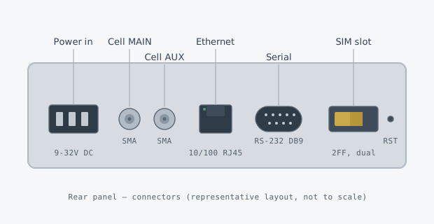
Screw both antennas onto the two SMA connectors — Cell MAIN and Cell AUX. Finger-tight is enough; don't use pliers. Always run with both connected: AUX is the receive-diversity path and dropping it can noticeably hurt throughput and stability in weak-signal spots.
3. Wire power and boot
Wire your DC supply to the terminal block — mind polarity (+ and − are marked). Anything from 9 to 32 V DC is fine; I run mine off a 12 V rail. Screw the plug in, apply power, and watch the front LEDs.
- Power solid green almost immediately.
- Status blinks amber while it boots (~40–60 s), then settles green.
- LTE and Signal come up once it registers on the network.
Full LED meanings are on the LED reference page.
4. Find the device IP
Connect your laptop to the Ethernet port. The rCell runs a DHCP server on the LAN by default, so you should get a 192.168.2.x lease. The device itself lives at:
Default gateway / web UI:  192.168.2.1
LAN subnet:                192.168.2.0/24
DHCP pool:                 192.168.2.100 - 192.168.2.200 (default)
If you set a static address on your laptop instead, use something like 192.168.2.50/24 with gateway 192.168.2.1. Confirm you can reach it:
# from your laptop
$ ping 192.168.2.1
$ curl -kI https://192.168.2.1/
Forgot a changed IP or password? Hold the recessed RST pinhole for ~30 seconds while powered to factory-reset. That restores 192.168.2.1 and default credentials.
5. Log into the web UI
Browse to https://192.168.2.1. You'll get a certificate warning because the device ships with a self-signed cert — expected, accept it for local access. The UI presents a standard admin sign-in prompt. First-boot units typically require you to set a new admin password before anything else; do that and store it in your password manager.
Once in, the dashboard shows registration state, the carrier/APN in use, signal metrics (RSSI/RSRP/RSRQ/SINR), the assigned WAN IP, and uptime. That's your at-a-glance health screen.
Note: I don't reproduce the login screen here on purpose — this is just documentation. Configure the device against the real UI on your own hardware.
6. Initial APN configuration
Most modern SIMs auto-detect their APN, but for MVNO / IoT data plans you usually have to set it by hand. In the UI it's under Cellular → APN / Connection. Enter the APN string your provider gave you (and username/password/auth only if they specified them — most IoT APNs need none).
Some generic examples — use the value your own carrier documents, these are just for shape:
| Carrier type | APN | Auth | Notes |
|---|---|---|---|
| Generic consumer LTE | internet | None | Often auto-detected |
| IoT / M2M data plan | iot.example.net | None / PAP | Frequently a static/private APN |
| MVNO example | data.mvno.example | PAP: user / pass | Only if provider specifies |
Prefer the CLI or serial console? You can push the same PDP context with a standard AT command. Connect over SSH or the RS-232 port (115200 8N1) and drop into the modem's AT interface:
# Define PDP context 1 with your APN
AT+CGDCONT=1,"IP","iot.example.net"
OK

# (optional) set auth if the carrier requires PAP/CHAP
AT$QCPDPP=1,1,"pass","user"
OK

# bring the context up / check attach
AT+CGATT?
+CGATT: 1
OK
Save and let the interface reconnect. On the dashboard the WAN IP should populate within a few seconds of a successful attach.
7. Verify signal and connectivity
Before you close the lid, sanity-check the radio. The quick one is AT+CSQ — it returns an RSSI index (0–31; higher is better, 99 = unknown):
AT+CSQ
+CSQ: 22,99          # 22 -> roughly -68 dBm, solid
OK

# richer per-technology serving-cell info
AT+CESQ
+CESQ: 99,99,255,255,28,52
OK
Rough RSSI reading of AT+CSQ: <10 marginal, 10–14 usable, 15–19 good, 20+ strong. If you're marginal, reposition the antennas (vertical, away from metal) before blaming the carrier. Then confirm end-to-end reachability from a device on the LAN:
$ ping -c3 1.1.1.1
$ curl -s https://ifconfig.co        # shows your carrier WAN IP
$ traceroute 1.1.1.1                  # first hop is a carrier CGNAT gateway
Heads-up on CGNAT: most carriers hand out a private, carrier-NAT address, so inbound connections won't work out of the box. If you need to reach the site from outside, you'll want a static/public-IP SIM or an outbound tunnel — see the port-forwarding note.